Monolithic full bridge autoresonant transmitter IC simplifies wireless battery charger design
The use of batteries in everyday devices is getting more ubiquitous. In many of these products, a charging connector is difficult or impossible to use. For example, some products require sealed enclosures to protect sensitive electronics from harsh environments and enable convenient cleaning or sterilisation. Other products may simply be too small to include a connector, and in products where the battery-powered application includes movement or rotation, forget about charging with wires. Wireless charging adds value, reliability, and robustness in these and other applications.
There are many ways to deliver power wirelessly. Across a short distance of less than a few inches, capacitive or inductive coupling is commonly used. In this article, solutions using inductive coupling are discussed.
In a typical inductively coupled wireless power system, an ac magnetic field is generated by a transmit coil, which then induces an alternating current in a receive coil just like a typical transformer system. The main difference between a transformer system and a wireless power system is that an air gap or other nonmagnetic material gap separates the transmitter and receiver. Furthermore, the coupling coefficient between the transmit coil and the receive coil is typically very low. Whereas a coupling of 0.95 to 1 is common in a transformer system, the coupling coefficient in a wireless power system varies from 0.8 to as low as 0.05.
Wireless Battery Charging Basics
A wireless power system is composed of two parts separated by an air gap: transmit (Tx) circuitry, including a transmit coil, and receive (Rx) circuitry, including a receive coil.
When designing a wireless power battery charging system, a key parameter is the amount of power that actually adds energy to the battery. This received power depends on many factors including:
- Amount of power being transmitted
- Distance and alignment between the transmit coil and the receive coil, commonly represented as the coupling factor between the coils
- Tolerance of the transmit and receive components
The main goal in any wireless power transmitter design is the ability for the transmit circuit to generate a strong field to guarantee delivery of the required received power under worst-case power transfer conditions. However, it is equally important to avoid thermal and electrical overstress in the receiver during best-case conditions. This is especially important when output power requirements are low and the coupling is great. An example would be a battery charger when the battery is fully charged with a receive coil placed close to the transmit coil.
A Simple but Complete Transmitter Solution Using the LTC4125
The LTC4125 transmitter IC is designed to pair with one of the various battery charger ICs in the Power by Linear™ portfolio as the receiver; for example, the LTC4120 – a wireless power receiver and battery charger IC.
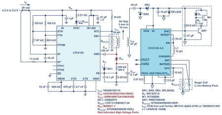
Figure 1. LTC4125 driving a 24μHz transmit coil at 103kHz, with 1.3A input current threshold, 119kHz frequency limit, and 41.5°C transmit coil surface temperature limit in a wireless power system with LTC4120-4.2 as a 400mA single cell Li-Ion battery charger at the receiver.
The LTC4125 comes with all of the features necessary for a simple, powerful, and safe wireless power transmitter circuit. In particular, it has the ability to adjust its output power, depending on the receiver load requirement, as well as to detect the presence of a conductive foreign object.
As mentioned earlier, the transmitter in a wireless battery charger system needs to generate a strong magnetic field in order to guarantee delivery of power under worst-case power transfer conditions. To meet this goal, the LTC4125 employs a proprietary autoresonant technology.
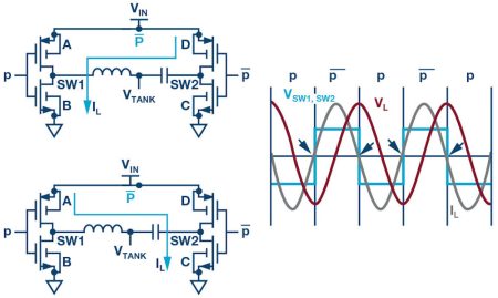
Figure 2. LTC4125 autoresonant drive.
The LTC4125 autoresonant drive ensures that the voltage at each SW pin is always in phase with the current into the pin. Referring to Figure 2, when current is flowing from SW1 to SW2, switches A and C are on while switches D and B are off, and vice versa in reverse. Locking the driving frequency cycle by cycle with this method ensures that the LTC4125 always drives the external LC network at its resonant frequency. This is true even with continuously changing variables that affect the resonant frequency of the LC tank such as temperature and the reflected impedance of a nearby receiver.
With this technology, the LTC4125 continually adjusts the driving frequency of the integrated full bridge switches to match the actual resonant frequency of the series LC network. In this fashion, the LTC4125 is able to efficiently build a large amplitude ac current in the transmitter coil without the need of a high dc input voltage, nor of a highly precise LC value.
The LTC4125 also adjusts the pulse width of the waveform across the series LC network by varying the duty cycle of the full bridge switches. By adjusting the duty cycle higher, more current is generated in the series LC network and therefore more power is available to the receiver load.

Figure 3. LTC4125 pulse width sweep – voltage and current in the Tx coil increases as the duty cycle is increased.
The LTC4125 performs a periodic sweep of this duty cycle to find the optimum operating point for the load condition at the receiver. This optimum power point search allows operation tolerant of a large air gap and misalignment of the coils while avoiding thermal and electrical over- stress to the receiver circuit in all cases. The period between each sweep is easily programmable with a single external capacitor.
The system shown in Figure 1 is quite tolerant of considerable misalignment. When the coils are misaligned significantly, the LTC4125 is able to adjust the generated magnetic field strength to ensure that the LTC4120 receives the full charge current. In the system shown in Figure 1, up to 2W can be transmitted at a distance of up to 12mm.
Foreign Conductive Object Detection
Another essential feature of any viable wireless power transmit circuit is the ability to detect the presence of a conductive foreign object placed in the magnetic field generated by the transmit coil. A transmit circuit designed to deliver more than a few hundred milliwatts to the receiver needs the ability to detect the presence of conductive foreign objects in order to prevent eddy current from forming in the object and causing undesirable heating.
The autoresonant architecture of the LTC4125 allows a unique method for the IC to detect the presence of a conductive foreign object. A conductive foreign object reduces the effective inductance value in the series LC network. This causes the autoresonant driver to increase the integrated full bridge driving frequency.
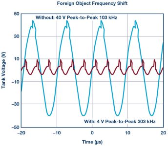
Figure 4. Comparison of the LTC4125 transmitter LC tank voltage frequency with and without the presence of a conductive foreign object.
By programming a frequency limit via a resistor divider, the LTC4125 reduces the driving pulse width to zero for a period of time when the autoresonant drive exceeds this frequency limit. In this fashion, the LTC4125 stops delivery of any power when it detects the presence of a conductive foreign object.
Note that by using this frequency shift phenomenon to detect the presence of a conductive foreign object, the detection sensitivity can be directly traded off with the component tolerance of the resonant capacitor (C) and the transmit coil inductance (L). For a typical 5% initial tolerance on each of the L and C values, this frequency limit can be programmed at 10% higher than the expected natural frequency from the typical LC value for a reasonably sensitive foreign object detection and robust transmitter circuit design. However, tighter tolerance 1% components can be used with the frequency limit set at only 3% higher than the typical expected natural frequency for a higher detection sensitivity while still maintaining the robustness of the design.
Power Level Flexibility and Performance
With some simple resistor and capacitor value changes, the same application circuit can be paired with a different receiver IC for higher wattage charging.
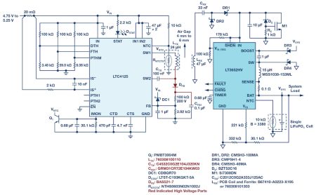
Figure 5. A diagram of the LTC4125 driving a 24μHz transmit coil at 103kHz, 119kHz frequency limit, and 41.5°C transmit coil surface temperature limit in a wireless power system with LT3652HV as a 1A single cell LiFePO4 (3.6V float) battery charger at the receiver.
Due to the high efficiency full bridge driver on the transmit circuit, as well as the high efficiency buck switching topology of the receive circuit, overall system efficiency as high as 70% can be achieved. This overall system efficiency is calculated from the dc input of the transmit circuit to the battery output of the receive circuit. Note that the quality factor of the two coils, as well as their coupling, is just as important to the overall efficiency of the system as the rest of the circuit implementation.
All of these features in the LTC4125 are achieved without any direct communication between the transmitter and receiver coils. This allows for a simple application design, covering various power requirements up to 5W as well as many different physical coil arrangements.
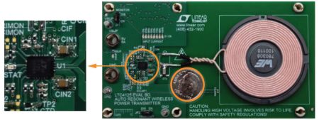
Figure 6. Typical complete wireless power transmitter board using LTC4125.
Figure 6 showcases the small overall size of the typical LTC4125 application circuit as well as its simplicity. As mentioned before, most of the features are customisable using external resistors or capacitors.
Conclusion
The LTC4125 is a powerful IC that provides all of the features necessary to make a safe, simple, and highly efficient wireless power transmitter. The autoresonant technology, optimum power search, and the conductive foreign object detection via frequency shift ease the design of a full-featured wireless power transmitter with excellent distance and alignment tolerance. The LTC4125 is a simple and exceptional choice in a robust wireless power transmitter design.
About the Author
Eko Lisuwandi has been a design engineer at the Analog Devices Boston Design Center since 2002. Eko spent his early career developing supervisory and high voltage power path mixed-signal products in CMOS technology. Later on, his interest expanded to include multichannel bipolar power converters. Now as a technical asset manager and section lead, Eko’s responsibility includes research, design, and development of battery chargers and wireless power integrated circuits in BiCMOS. He received his B.S. in 2001 and M.Eng. degree in 2002, both in electrical engineering and computer science from MIT. He can be reached at eko.lisuwandi@analog.com.


