Vehicle Tracking Systems: Anytime, Anywhere, Anyhow

A vehicle tracking system is ideal for monitoring either a single car or an entire fleet of vehicles. A tracking system consists of automatic tracking hardware and software for data collection (and data transmission if required). The global fleet management market size was valued at USD $8 billion in 2015 and is anticipated to exceed USD $22 billion by 2022, growing at a CAGR of over 20% from 2016 to 2023 (Source: Global Market Insights). The rising demand for commercial vehicles in regions such as Latin America, the Middle East, and Africa also represents a potential growth opportunity. In more developed regions such as Europe and North America, integration of Internet of Things (IoT) technology in vehicles is expected to boost the adoption rate of vehicle tracking systems, although the high cost of integration has slowed this progress. Further, the Asia Pacific vehicle tracking market size is anticipated to witness significant growth over the forecasted period, with Japan, India, and China being the primary driving countries. These emerging markets have high potential, primarily due to their many commercial vehicles.

Active vs. Passive Trackers
Active and passive trackers collect data in the same way and are equally accurate. The main difference between the two types involves time. Active trackers are also called real-time trackers, because they transmit data via satellite or a cellular network, which instantly indicates where the vehicle is located. In this way, a computer screen can display this movement in real-time. This makes active tracking the best choice for businesses interested in improving the efficiency of their deliveries and monitoring their employees driving in the field. An active tracker also has geo-fence capabilities (think of this feature like a force field), providing an alert when the vehicle enters or exits a predetermined location (Source: RMT Corporation). These kinds of systems can also help prevent theft and help recover stolen vehicles. Of course, active GPS tracking devices are more expensive than passive ones and require a monthly service fee.

Passive trackers, on the other hand, are less costly, are smaller, and are easier to conceal. Their downside is that they have limited data storage. They store the information on the device instead of transmitting the data to a remote location. The tracker must be removed from the vehicle and plugged into a computer to view any of its information. These systems are good for people tracking their mileage for work purposes, or for businesses interested in reducing the misuse of their vehicles. Also, they are often chosen for monitoring the actions of people as well (think of detective work). Passive trackers are a good choice if immediate feedback is not required and there is a plan to regularly check the device’s data.

Both types of trackers are portable in nature and have a relatively small form factor. Therefore, battery power is required, as is backup capability to preserve data in case of power loss. Due to the higher automotive system voltages and currents required to charge the battery (typically a single-cell Li-ion cell), a switchmode charger is desirable for its higher charging efficiency when compared to a linear battery charging IC, as less heat in the form of power dissipation is generated. In general, embedded automotive applications have input voltages up to 30 V, with some even higher. In these GPS tracking systems, a charger with the typical 12 V to single-cell Li-ion battery (3.7 V typical) with added protection to much higher input voltages (in case of voltage transients from battery excursions), plus some sort of backup capability would be ideal.

Design Issues for Battery Charging ICs
Traditional linear topology battery chargers are often valued for their compact footprints, simplicity, and modest cost. However, drawbacks of traditional linear chargers have included limited input and battery voltage ranges, higher relative current consumption, excessive power dissipation (heat generation), limited charge termination algorithms, and lower relative efficiency. On the other hand, switchmode battery chargers are popular choices due to their topology, flexibility, multichemistry charging, their high charging efficiencies that minimise heat to enable fast charge times, and their wide operating voltage ranges. Of course, trade-offs always exist. Some downsides of switching chargers include relatively high cost, more complicated inductor-based designs, potential noise generation, and larger footprint solutions. Modern lead acid, wireless power, energy harvesting, solar charging, remote sensor, and embedded automotive applications are predominantly powered by switchmode chargers for the positive reasons stated previously.

Traditionally, a tracker’s backup power management system for batteries consisted of multiple ICs, a high voltage buck regulator, and a battery charger, plus all the discrete components; not exactly a compact solution. Hence, early tracking systems were not very compact in form factor. A typical application for a tracking system uses an automotive battery and a 1-cell Li-ion battery for storage and backup.

Why is it then that a more highly integrated power management solution is needed for tracking systems? Primarily, it is needed to reduce the size of the tracker itself; smaller is better in this market. Furthermore, there are requirements for safely charging the battery and protecting the IC against voltage transients, a need for system backup in case system power goes away or fails, and for powering the relatively lower rail voltages of the general packet radio service (GPRS) chipsets at ~4.45 V.

Power Backup Manager

An integrated power backup manager and charger solution, which solves the outlined objectives requires the following attributes:
. Synchronous buck topology for high efficiency
. Wide input voltage range to accommodate a variety of input power sources, plus protection against high voltage transients
. Proper battery charge voltage to support the GPRS chipset
. Simple and autonomous operation with onboard charge termination (no microcontroller needed)
. PowerPath control for seamless switchover between input power and backup power during a power fail event; it also needs to provide reverse blocking if a shorted input occurs
. Battery backup capability for system load power when the input is not present or fails
. Small and low profile solution footprints due to space constraints
. Advanced packaging for improved thermal performance and space efficiency

To address these specific needs, Analog Devices recently introduced the LTC4091—a complete, Li-ion battery backup management system for 3.45 V to 4.45 V supply rails that must be kept active during a long duration main power failure. The LTC4091 employs a 36 V monolithic buck converter with adaptive output control to provide power to the system load and enable high efficiency battery charging from the buck output. When external power is available, the device can provide up to 2.5 A of total output current and up to 1.5 A of charge current for a single-cell, 4.1 V or 4.2 V Li-Ion battery. If the primary input source fails and can no longer power the load, the LTC4091 provides up to 4 A to the system output load from the backup Li-ion battery via an internal diode, and relatively unlimited current if an external diode transistor is used. To protect sensitive downstream loads, the maximum output load voltage is 4.45 V. The device’s PowerPath control provides a seamless switchover between input power and backup power during a power fail event and enables reverse blocking with a shorted input. Typical applications for the LTC4091 include fleet and asset tracking, automotive GPS data loggers and telematics systems, security systems, communications, and industrial backup systems.

The LTC4091 includes 60 V absolute maximum input overvoltage protection, making the IC immune to high input voltage transients. The LTC4091’s battery charger provides two pin selectable charge voltages optimized for Li-ion battery backup applications: the standard 4.2 V and a 4.1 V option that trades off battery run time for increased charge/discharge cycle life. Other features include soft-start and frequency fold-back to control output current during startup and overload, as well as trickle charge, automatic recharge, low battery precharge, charge timer termination, thermal regulation, and a thermistor pin for temperature-qualified charging.

The LTC4091 is housed in a low profile (0.75 mm) 22-lead 3 mm × 6 mm DFN package with a backside metal pad for excellent thermal performance. The device operates from –40°C to +125°C. Figure 1 shows its typical application schematic.


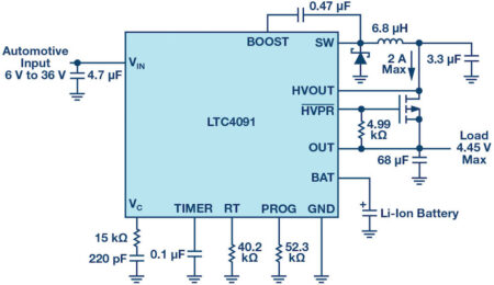
Figure 1. LTC4091 typical application schematic.

Thermal Regulation Protection
To prevent thermal damage to the IC or surrounding components, an internal thermal feedback loop automatically decreases the programmed charge current if the die temperature rises to approximately 105°C. Thermal regulation protects the LTC4091 from excessive temperature due to high power operation or high ambient thermal conditions, and allows the user to push the limits of the power handling capability with a given circuit board design without risk of damaging the LTC4091 or external components. The benefit of the thermal regulation loop is that charge current can be set according to actual conditions, rather than worst-case conditions with the assurance that the battery charger will automatically reduce the current in worst-case conditions.
Automotive Cold-Crank Ride Through
Automotive applications experience large dips in supply voltage, such as during a cold-crank event, which can cause the high voltage switching regulator to lose regulation, resulting in excessive VC voltage and consequently excessive output overshoot when VIN recovers. To prevent overshoot when recovering from a cold-crank event it is necessary to reset the LTC4091’s soft-start circuit via the RUN/SS pin. Figure 2 below shows an example of a simple circuit that automatically detects a brown-out condition and resets the RUN/SS pin, re-engaging the soft-start feature and preventing damaging output overshoot.


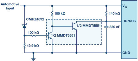
Figure 2. Cold-crank ride-through circuit.

Conclusion
The adoption rates of automotive and fleet vehicle tracking systems are on the rise. Modern tracker form factors have shrunk and features have grown to include active data transmission for real-time tracking. Furthermore, backup capability and lower voltages to power the system GPRS chipset are needed. Analog Devices’ LTC4091 is a high voltage, high current buck battery charger and PowerPath backup manager with thermal regulation and other extensive protection that comprises a 1-chip, compact, powerful, and flexible solution for vehicle tracking applications, thus making a designer’s task simpler and easier.

Steve Knoth [steve.knoth@analog.com] is a senior product marketing engineer in Analog Devices’ Power by Linear™ Group. He is responsible for all power management integrated circuit (PMIC) products, low dropout regulators (LDOs), battery chargers, charge pumps, charge pump-based LED drivers, supercapacitor chargers, low voltage monolithic switching regulators, and ideal diode devices. Prior to joining Analog Devices (former Linear Technology) in 2004, Steve had held various marketing and product
engineering positions since 1990 at Micro Power Systems, Analog Devices, and Micrel Semiconductor. He earned his bachelor’s degree in electrical engineering in 1988 and a master’s degree in physics in 1995, both from San Jose State University. Steve also received an M.B.A. in technology management from the University of Phoenix in 2000. In addition to enjoying time with his kids, Steve can be found tinkering with pinball/arcade games or muscle cars; and buying, selling, and collecting vintage toys and movie/
sports/automotive memorabilia.

> Read More

Semtech and GSA Optimise Logistics and Inventory Management with LoRaWAN®

Semtech Corporation has announced that Green Scale Alchemy (GSA), a leading developer of Internet of Things (IoT) solutions for asset management in the retail and supply chain industries, has integrated Semtech’s IoT devices operating on the LoRaWAN® protocol into its IoT-based pool management platform. The platform enables accurate pallet management to increase logistical efficiency and has already been rolled out by Giffard, a large-scale French liqueur manufacturer, to remotely manage its packaging assets and tools across two of the company’s large warehouses.

“By integrating IoT devices operating the LoRaWAN protocol, GSA is among the first in Europe to offer private networking capabilities and flexible devices to meet the needs of today’s supply chain managers,” said Frédéric Sammut, CEO at GSA. “Leveraging the LoRaWAN protocol provides accurate inventory data over long range, enabling managers to increase the efficiency of their logistical processes to reduce associated costs and increase sustainability.”

“GSA’s innovative solutions based on the LoRaWAN protocol enabled Giffard to transform its existing packaging and pallets into connected assets through innovative and simple retrofit. This allowed improved fleet management and the allocation of resources with integrated tools for more efficient production,” said Pierre Jouanneau Giffard, COO at Giffard. “Increased management efficiency allowed Giffard to optimise its workforce and material resources to improve profits.”

A standard in the logistics industry, wooden pallets deliver an estimated 95 percent of Europe’s consumer goods. GSA identified the shortcomings of legacy pallet-based shipping and developed its solution to leverage LoRaWAN networks to optimize the remote management of pallets in real time.

GSA’s platform based on the LoRaWAN protocol delivers comprehensive insight into the location and environmental status of the individual pallet, including geolocation capabilities to identify pallet location in a warehouse or in transit. This reliable data enables managers to track assets through the supply chain from manufacturing to distribution and out for delivery. Additionally, amid the ongoing COVID-19 pandemic, smarter logistics management and geolocation in warehouses allows organisations to move assets only when necessary and keep employees safe through social distancing.

In June 2017, Giffard deployed GSA’s solution to its newest liqueur production plant, a state-of-the-art site that manufacturing up to 20,000 bottles per day. The plant consists of two 3,000 square meter buildings dedicated to liqueur production and warehousing respectively. By utilising the IoT platform, Giffard receives and audits its production data to identify inefficiencies in its warehousing workflow and as a result remotely manages all its packaging assets and tools within its sites.

“Integrating proven IoT geolocation solutions operating on LoRaWAN enables customers to reduce logistical inefficiencies and reduce cost,” said Marc Pegulu, Vice President of IoT Product Marketing in Semtech’s Wireless and Sensing Products Group. “By developing its solution to utilise the LoRaWAN protocol, GSA created a flexible, scalable IoT platform that monitors and reports pallet status, condition and location in real time. These enhanced metrics help keep inventory safe and accounted for throughout the management cycle and deliver customers a faster ROI.”

To learn more about LoRa devices, visit the Semtech website.

About Semtech’s LoRa® Platform

Semtech’s LoRa device-to-Cloud platform is a globally adopted long range, low power solution for IoT applications, enabling the rapid development and deployment of ultra-low power, cost efficient and long range IoT networks, gateways, sensors, module products, and IoT services worldwide. Semtech’s LoRa devices provide the communication layer for the LoRaWAN® protocol, which is maintained by the LoRa Alliance®, an open IoT alliance for Low Power Wide Area Network (LPWAN) applications that has been used to deploy IoT networks in over 100 countries. Semtech is a founding member of the LoRa Alliance. To learn more about how LoRa enables IoT, visit Semtech’s LoRa site.

> Read More

2G to 5G Base Station Receiver Design Simplified by Innovative Integrated Transceivers

Base station receiver design can be a daunting task. Typical receiver components such as mixers, low noise amplifiers (LNAs), and analog-to-digital converters (ADCs) have progressively improved over time. However, architectures have only changed slightly. The limitation in architectural choices have held back base station designers from differentiating their products in the marketplace. Recent product developments, particularly integrated transceivers, have significantly relaxed some of the constraints of even the most challenging base station receiver designs. The new base station architecture offered by these transceivers allows base station designers more choices and ways to differentiate their product.

The family of integrated transceivers discussed in this article are the industry’s first to support all existing cellular standards, 2G to 5G, and cover the full sub-6 GHz tuning range. These transceivers allow base station designers to adopt a single, compact radio design across all band and power variants.

First, let’s review several base station classes. The well-known standards body 3GPP has several defined base station classes. These base station classes go by various names. In broad terms, the largest base stations, or wide area base stations (WA-BS), offer the most geographical coverage and number of users. They also output the highest power and must provide the best receiver sensitivity. Each progressively smaller base station requires less output power and a relaxed receiver sensitivity.

Table 1. Table 1. Various Base Station Sizes

In addition, 3GPP also defines different modulation schemes. Broadly speaking, a practical breakdown of modulation schemes is into non-GSM (including LTE and CDMA types of modulation) and GSM-based modulation—particularly multicarrier GSM (MC-GSM). Of the two broad schemes, GSM is the most demanding in terms of RF and analog performance. Also, as higher throughput radios have become more common, MC-GSM has become the norm over the single carrier GSM case. Generally, a radio front end in a base station that can support MC-GSM performance can also handle non-GSM performance. Carriers that handle MC-GSM will have more flexibility in market opportunities.

Historically, base stations have been composed of discrete components. We believe today’s integrated transceivers can replace many discrete components and offer system advantages as well. But first, we need to discuss the challenges of base station receiver design.

The wide area or macrobase station has traditionally been the most challenging and expensive receiver design, and historically has been the workhorse of our wireless communications networks. What makes it so challenging? In a word, sensitivity.

A base station receiver must achieve desired sensitivity under specific conditions. Sensitivity is a figure of merit of how well a base station receiver can demodulate a desired weak signal from handsets. Think of sensitivity as determining the farthest a base station can get from a handset while maintaining a connection. Sensitivity can be categorized in two ways: 1) static sensitivity without any external interference and 2) dynamic sensitivity with interference.

Let’s focus on static sensitivity, first. In engineering parlance, sensitivity is determined by the system noise figure (NF). A lower noise figure means better sensitivity. The desired sensitivity is achieved by increasing gain to achieve the desired system NF, and gain is generated by an expensive component called a low noise amplifier (LNA). The higher the gain, the more an LNA costs in dollars and power.

Unfortunately, there’s a trade-off with dynamic sensitivity. Dynamic sensitivity means that static sensitivity can get worse with interference. Interference is any unwanted signal that appears at the receiver, including signals from the outside world or signals generated unintentionally by the receiver, such as intermodulation products. Linearity in this context describes how well a system can handle interference.

In the presence of interference, our system loses the sensitivity we worked so hard to achieve. This trade-off gets worse with higher gain, because gain typically comes with lower linearity. In other words, too much gain degrades linearity performance, which leads to sensitivity degradation under strong interference.

Wireless communication networks are designed such that the burden of network performance is on the base station side as opposed to the handset side. WA-BSs are designed to cover a large area and achieve excellent sensitivity performance. A WA-BS must have the best static sensitivity to support handsets at the cell edge where the signal from handset is very weak. On the other hand, under interference or blocking conditions a WA-BS receiver’s dynamic sensitivity still needs to be good. The receiver still must exhibit good performance on a weak signal from a handset, even while a strong signal from a handset near the base station generates interference.

The following signal chain is a simplified typical discrete component-based system receiver. The LNA, mixer, and variable gain amplifier (VGA) are referred to as the RF front end. The RF front end is designed with a noise figure of 1.8 dB, while the ADC has a noise figure of 29 dB, and in the analysis in Figure 1, the RF front-end gain is swept on the x-axis to show the system sensitivity.

Figure 1. Typical discrete receiver signal chain, simplified.

Now let’s compare a simplified transceiver receive signal chain. One can see the transceiver receive signal chain bill of materials is smaller than the comparable discrete component signal chain. Additionally, the transceivers are designed with two transmitters and two receivers on chip. The apparently simple integration hides the elegance of the receiver design, which typically achieves a 12 dB noise figure. The following analysis shown in Figure 2 will show how the sensitivity pays off in a system.

Figure 2. Typical transceiver/receiver signal chain, simplified.

Figure 3 shows the RF front-end gain vs. static sensitivity for the above two implementations. A WA-BS works in the region where the sensitivity is almost to meet tightest sensitivity requirement. In contrast, a small cell works where the sensitivity curve slope is steepest, while still meeting the standard with a small margin. The transceiver achieves the desired sensitivity with much less RF front-end gain for both the WA-BS and small cell.

Figure 3. Discrete receiver vs. transceiver/receiver sensitivity.

What about dynamic sensitivity? In the RF front-end gain region, where we would design wide area base stations using a transceiver, dynamic sensitivity is also much better than a discrete solution. This is because lower gain RF front ends typically have higher linearity at a given power consumption. In discrete solutions, which typically use high gain, linearity is often dominated by the RF front end. In transceiver designs, degradation in sensitivity due to interference is dramatically reduced compared to a discrete solution.

It’s worth mentioning that in the presence of too much interference, systems are designed to reduce gain to a point where the interference can be tolerated and increase the gain when the interference is reduced. This is referred to as automatic gain control (AGC). Any reduction in gain is also going to reduce the sensitivity. If a system can tolerate the interferers, it is often best to keep the gain as high as possible to maximize sensitivity. AGC is a topic for a future discussion.

In summary, two outstanding features of this class of transceivers are excellent noise figure and higher immunity to interference. Using a transceiver in your signal chain means you can achieve a desired static sensitivity with much less front-end gain. In addition, the lower level of interference means you can achieve better dynamic sensitivity. If you need a LNA at all, it will be a less costly LNA and consume less power. You can also make different design trade-offs elsewhere in the system to take advantage of these features.

Today, there are configurable transceiver products in the market that fill a role in both wide area and small cell base station designs. Analog Devices is taking a leadership role in this new approach, with ADRV9009 and ADRV9008 products are
well-suited for wide area base stations and MC-GSM levels of performance. Additionally, the AD9371 family offers options with non-GSM (CDMA, LTE)  performance and bandwidth, but more power optimization.

This article is far from a thorough overview. The topic of sensitivity will receive a deeper treatment in our follow-up articles. Additionally, other challenges in base station receiver design include automatic gain control (AGC) algorithms, channel estimation, and equalization algorithms, etc. We plan to follow this article with a series of technical articles with the aim of simplifying your design process and improving your receiver system understanding.

About the Authors

Jon Lanford works as a system and firmware verification manager in the Transceiver Product Group at Analog Devices Greensboro. He has worked at ADI since completing his master’s degree in electrical engineering from North Carolina State University in 2003. His previous engineering roles include gigasample pipeline ADC design and calibration algorithm design, as well as test development for transceivers. He can be reached at jonathan.lanford@analog.com.

Kenny Man’s 25 year career has spanned across system design on high speed instrumentation and wireless base stations, system applications, and system architecture for wireless infrastructure in telecom equipment companies and semiconductor companies. His present role is in product engineering where he wants to better contribute to the building blocks of communication infrastructure. His hobbies include hiking, snow skiing, and reading history. He can be reached at kenny.man@analog.com.

> Read More

Mouser Electronics presents new resource site dedicated to LoRaWAN technology

Mouser Electronics has created a new resource site dedicated to the LoRaWAN® standard and its capabilities, applications, and related products. Engineers and designers can access the comprehensive new site by visiting https://resources.mouser.com/lora.

LoRaWAN is a low-power, wide-area (LPWA) network protocol designed to provide internet connections to battery-operated devices in regional, national, and global networks. The high-performance protocol supports key Internet of Things (IoT) requirements including end-to-end security, bi-directional communication, mobility, and localisation services. The new resource site from Mouser offers a broad range of useful information on LoRaWAN technologies, strategies, and devices, providing designers with a single home for advice and insights.

Through standardisation and an accredited certification scheme, the LoRa Alliance® delivers the interoperability needed for LPWA networks to scale, making LoRaWAN the premier solution for global LPWAN deployments. Mouser, as part of the TTI Family of Companies, has partnered with LoRa Alliance to deliver and promote this new standard in networking solutions.

With impressive low-power and security capabilities, the LoRaWAN specification offers a wide variety of use cases with specific nuances for each design opportunity. Mouser’s new LoRaWAN resource site includes technical articles, videos, product descriptions, and instructional flipbooks, providing information on how to leverage LoRaWAN connectivity in agriculture, smart cities, sensors, autonomous vehicles, and other applications.

To visit Mouser’s new LoRaWAN technology resource site, visit https://resources.mouser.com/lora.

> Read More

About Smart Cities

This news story is brought to you by smartcitieselectronics.com, the specialist site dedicated to delivering information about what’s new in the Smart City Electronics industry, with daily news updates, new products and industry news. To stay up-to-date, register to receive our weekly newsletters and keep yourself informed on the latest technology news and new products from around the globe. Simply click this link to register here: Smart Cities Registration