At next week’s European Microwave Week (EuMW 2023), Rohde & Schwarz will introduce a radar test system which simulates driving scenarios for testing radar-based advanced driver assistance systems (ADAS) and radar sensors used in automated driving cars over the air.
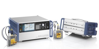
New options for the company’s R&S AREG800A automotive radar echo generator and the R&S QAT100 antenna array generate “extremely short distances” for the artificial objects, and therefore enables realistic autonomous braking tests with the smallest distance possible, claimed Rohde & Schwarz.
The radar test system can be used for radar object simulation, from single sensor tests to 360 degree environments, covering 76 to 81GHz for automotive radar sensors. Its scalability and adaptability allow a range of ADAS traffic scenarios to be electronically generated along the whole testing lifecycle.
It also enables tests currently performed in real-world test drives to be relocated to the lab, enabling errors to be detected at an early stage and delivering significant cost savings.
The R&S AREG800A automotive radar echo generator operates as a backend and the R&S QAT100 antenna array acts as a frontend in the systems which can be used in benchtop development, hardware-in-the-loop and vehicle-in-the-loop. For production, the R&S AREG800A automotive radar echo generator operates as a backend and the R&S AREG8-24/81S/D antenna is a frontend.
The AREG800A is claimed to provide a higher instantaneous bandwidth to improve the distance resolution. With the mmW remote frontends R&S AREG8-81S/D, the instantaneous bandwidth will be extended from 4.0 to 5GHz, offering a future proof solution so that the users can measure their automotive radars using a higher bandwidth.
A new feature for near object range allows minimum distance of one or more artificial objects to be reduced down to the airgap value of the radar under test.
For the R&S QAT100 a new option is R&S QAT-B1 Enhanced Flatness. It contains a detailed characterisation of each antenna of the QAT frontends. With this option, the accuracy of the amplitude flatness of all antennas is improved when operated with R&S AREG800A.